This is where all information about Antennas, grounding, Counterpoises reside

this is what I refer to as the main section of the antenna. check yours and reply here to let me know what state your coax is in? it is wet, touching the trees, is it bent? did you solder it perfect?
I always use the arrl antenna book when i am soldering coax. check it out.
ps: check out facebook.com/ylrl
33
got picture from http://www.jpole-antenna.com thank you
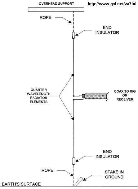
this is a dipole I am planning on making.... (made it and it worked VERY GOOD) 1:1
Vertical Dipole for 15 Meters and would love to make one also for 10 meters.
feet = 468/28.390 = 16.50 feet 10 meters
feet = 468/21.325 = 22 feet 15 meters
I have 10 gauge shielded wire (good stuff) for verticals
ka1uln
here are the notes from the May 21 presentation
session May 21, 2015 echolink 8 pm Yl NFarl-r
Grounding (RODS and Ribbons)
May 21, 2015 YLRL echolink net
An effective ground system is necessary for every amateur station.
The mission of the ground system is twofold. FIRST, it reduces the possibility of electrical shocks if something in a piece of equipment should fail and the chassis or cabinet become “HOT.” If connected properly, three-wire electrical systems ground the chassis. A ground system to prevent shock hazard is generally referred to as “DC GROUND.”
The second job the ground system must perform is to provide a low-impedance path to ground for any stray RF current inside the station. Stray RF can cause equipment to malfunction and contributes to RFI problems. This low-impedance path is usually called “RF GROUND.”
The first step in building a ground system is to bound together the chassis of all equipment in your station. Ordinary hookup wire will do for a dc ground, but for a good RF ground you need a low-impedance conductor, COPPER STRAP sold as 'flashing copper,” is excellent for this application, it maybe hard to find. Braid for coaxial cable is popular choice; it is readily available, makes a low-impedance conductor, and is flexible. You see this on roofs in south and west.
Grounding straps can be run from equipment chassis to equipment chassis.1/2 copper water pipe runs entire length of operating bench. A thick braid from RG-8 cable runs from each piece of equipment to a clamp on the pipe.
After equipment is bonded to common ground bus the ground bus must be wired to a good earth ground. This run should be with heavy conductor (braid – I CALL RIBBON) should be short and direct as possible.
Drive one or more grounds rods into earth where conductor leaves the house. Ground rods-8 to 10 feet can be acquired from electrical supply house (home depot or lowe's or the like) steel with heavy copper plating.
Once rod is in ground clamp the conductor from the station ground bus to it with a clamp that can be tightened securely and will NOT RUST. Copper-plated clamps made specifically for this purpose can be found and electrical supply stores. If possible solder the connection.
ANOTHER popular station ground is the COLD (not hot) water pipe system in the building.
Length of of ground wire should be multiple of ¼ wave.
Ground noise:
Noise in ground systems can affect sensitive radio equipment. It is usually related to one of three problems:
1. Insufficient ground conductor wire
2. Loose ground connections or
3. Ground loops
liberal use lock washer and star washers is highly recommended
Ground noise can affect receive and transmitted signals
The antennas that we mount are affected by the presence of ground. At times, the ground is a reflector and at other times, it is an absorber.
The ground around the base of a quarter wave vertical antenna needs considerable help in the form of radials, if this type of antenna is to perform well.
When an antenna that is a near ground radiates, some of the energy will strike the ground and some of the energy will be reflected. The reflected energy will bounce back to the antenna and effect the pattern of current distribution in the radiator, and thus effect the pattern and the feedpoint impedance of the antenna.
After antennas, station grounding is probably the most discussed subject in amateur radio and it is also the one replete with the most misconceptions. The first thing to know is that there are three functions served by grounding in ham shacks: 1. Electrical Safety 2. Stray RF Suppression (or simply RF Grounding) 3. Lightning Protection. Each has it's own set of requirements, but not all station setups need every kind of ground. In fact, some setups don't use a ground at all! The articles on this page will help clear up some of the myths and mystery surrounding this popular topic.
Grounds fulfill three distinct functions. The best ground for one function isn't necessarily the best for another. The three are:
a. Safety ground. This protects you from a shock hazard if one of the mains or high voltage power supply wires contacts the chassis due to some kind of fault. The requirements for this ground are spelled out in your state's electrical code. I believe that most states adopt the National Electrical Code (NEC). The safety ground conductor in your wall sockets should be connected to ground according to this code, and your rig's chassis should be connected to the safety ground.
b. Lightning ground. The requirements for a ground for lightning protection are much more stringent than for a safety ground. The topic has been discussed in this group many times, and there are numerous resources available for learning how to make a ground system for lightning protection. (See the TIS Page on Lightning Protection)
c. RF ground. This is required only for certain types of antennas-- ones which require current flow to ground to complete the antenna circuit. An example is a quarter-wave vertical. One wire of the feedline connects to the base of the antenna, and the other connects to ground. The connection to ground has to have a low RF resistance, or you'll expend too much of your power heating the ground. A few radial wires will provide a moderately low loss connection. A ground rod will help a little, but the RF resistance will be high, resulting in quite a bit of loss. Chapter 8 of the ARRL Antenna Book shows the approximate trade between resistance and number of radials. If your antenna is much shorter than ¼ wavelength, you'll need many, many radials to get reasonable efficiency. If it's longer, you can get by with fewer. A ½ wavelength base-fed vertical needs only a very modest ground, and a ground rod is adequate. The requirements for various other end-fed antennas depend on their length. If you use a "complete" antenna like a dipole or a ground plane (that is, one that doesn't require your feedline to connect to ground), you don't need a RF ground, as long as you keep common-mode currents off your feedline. A "current" or "choke" balun is most commonly used for this.
this is what I refer to as the main section of the antenna. check yours and reply here to let me know what state your coax is in? it is wet, touching the trees, is it bent? did you solder it perfect?
I always use the arrl antenna book when i am soldering coax. check it out.
ps: check out facebook.com/ylrl
33
got picture from http://www.jpole-antenna.com thank you
this is a dipole I am planning on making.... (made it and it worked VERY GOOD) 1:1
Vertical Dipole for 15 Meters and would love to make one also for 10 meters.
feet = 468/28.390 = 16.50 feet 10 meters
feet = 468/21.325 = 22 feet 15 meters
I have 10 gauge shielded wire (good stuff) for verticals
ka1uln
here are the notes from the May 21 presentation
session May 21, 2015 echolink 8 pm Yl NFarl-r
Grounding (RODS and Ribbons)
May 21, 2015 YLRL echolink net
An effective ground system is necessary for every amateur station.
The mission of the ground system is twofold. FIRST, it reduces the possibility of electrical shocks if something in a piece of equipment should fail and the chassis or cabinet become “HOT.” If connected properly, three-wire electrical systems ground the chassis. A ground system to prevent shock hazard is generally referred to as “DC GROUND.”
The second job the ground system must perform is to provide a low-impedance path to ground for any stray RF current inside the station. Stray RF can cause equipment to malfunction and contributes to RFI problems. This low-impedance path is usually called “RF GROUND.”
The first step in building a ground system is to bound together the chassis of all equipment in your station. Ordinary hookup wire will do for a dc ground, but for a good RF ground you need a low-impedance conductor, COPPER STRAP sold as 'flashing copper,” is excellent for this application, it maybe hard to find. Braid for coaxial cable is popular choice; it is readily available, makes a low-impedance conductor, and is flexible. You see this on roofs in south and west.
Grounding straps can be run from equipment chassis to equipment chassis.1/2 copper water pipe runs entire length of operating bench. A thick braid from RG-8 cable runs from each piece of equipment to a clamp on the pipe.
After equipment is bonded to common ground bus the ground bus must be wired to a good earth ground. This run should be with heavy conductor (braid – I CALL RIBBON) should be short and direct as possible.
Drive one or more grounds rods into earth where conductor leaves the house. Ground rods-8 to 10 feet can be acquired from electrical supply house (home depot or lowe's or the like) steel with heavy copper plating.
Once rod is in ground clamp the conductor from the station ground bus to it with a clamp that can be tightened securely and will NOT RUST. Copper-plated clamps made specifically for this purpose can be found and electrical supply stores. If possible solder the connection.
ANOTHER popular station ground is the COLD (not hot) water pipe system in the building.
Length of of ground wire should be multiple of ¼ wave.
Ground noise:
Noise in ground systems can affect sensitive radio equipment. It is usually related to one of three problems:
1. Insufficient ground conductor wire
2. Loose ground connections or
3. Ground loops
liberal use lock washer and star washers is highly recommended
Ground noise can affect receive and transmitted signals
The antennas that we mount are affected by the presence of ground. At times, the ground is a reflector and at other times, it is an absorber.
The ground around the base of a quarter wave vertical antenna needs considerable help in the form of radials, if this type of antenna is to perform well.
When an antenna that is a near ground radiates, some of the energy will strike the ground and some of the energy will be reflected. The reflected energy will bounce back to the antenna and effect the pattern of current distribution in the radiator, and thus effect the pattern and the feedpoint impedance of the antenna.
After antennas, station grounding is probably the most discussed subject in amateur radio and it is also the one replete with the most misconceptions. The first thing to know is that there are three functions served by grounding in ham shacks: 1. Electrical Safety 2. Stray RF Suppression (or simply RF Grounding) 3. Lightning Protection. Each has it's own set of requirements, but not all station setups need every kind of ground. In fact, some setups don't use a ground at all! The articles on this page will help clear up some of the myths and mystery surrounding this popular topic.
Grounds fulfill three distinct functions. The best ground for one function isn't necessarily the best for another. The three are:
a. Safety ground. This protects you from a shock hazard if one of the mains or high voltage power supply wires contacts the chassis due to some kind of fault. The requirements for this ground are spelled out in your state's electrical code. I believe that most states adopt the National Electrical Code (NEC). The safety ground conductor in your wall sockets should be connected to ground according to this code, and your rig's chassis should be connected to the safety ground.
b. Lightning ground. The requirements for a ground for lightning protection are much more stringent than for a safety ground. The topic has been discussed in this group many times, and there are numerous resources available for learning how to make a ground system for lightning protection. (See the TIS Page on Lightning Protection)
c. RF ground. This is required only for certain types of antennas-- ones which require current flow to ground to complete the antenna circuit. An example is a quarter-wave vertical. One wire of the feedline connects to the base of the antenna, and the other connects to ground. The connection to ground has to have a low RF resistance, or you'll expend too much of your power heating the ground. A few radial wires will provide a moderately low loss connection. A ground rod will help a little, but the RF resistance will be high, resulting in quite a bit of loss. Chapter 8 of the ARRL Antenna Book shows the approximate trade between resistance and number of radials. If your antenna is much shorter than ¼ wavelength, you'll need many, many radials to get reasonable efficiency. If it's longer, you can get by with fewer. A ½ wavelength base-fed vertical needs only a very modest ground, and a ground rod is adequate. The requirements for various other end-fed antennas depend on their length. If you use a "complete" antenna like a dipole or a ground plane (that is, one that doesn't require your feedline to connect to ground), you don't need a RF ground, as long as you keep common-mode currents off your feedline. A "current" or "choke" balun is most commonly used for this.
Radials:
Counterpoises:
Rods:

Besides one lead from inside the shack, the others go to several other well spaced ground rods, a lead to the tower base (which has it's own ground system), and finally, the power company ground, which is only about a foot away.
73
K9WN Jake
picture is taken from k9wn
Youtube video showing how to drive a 10 foot ground rod into the ground with water.
link>
Ribbons:
Is Your Radio Equipment REALLY Grounded?
You may believe your radio equipment, antenna and tower are well-grounded. After all, you drove the ground rods into the earth yourself and connected the ground wire to the rods with heavy-duty clamps.
With an ohmmeter, I measured an open circuit from the ground wire to its grounding clamp! This was true for both the equipment ground outside my radio room and for the ground at the base of my beam antenna.
I do understand that contact points oxidize and their resistance increases. But the ohmmeter's needle didn't move even on the instrument's X 1000 range! I had no grounds that worked!
military handbook on grounding, bonding and shielding: A PDF download
any questions contact ag4yl or KA1ULN
Grounding:
what kind of grounding do you have for your station?
Do you know what grounding is used for?
Please add your comments below about YOUR ground installation.
on May 21, at 8:00 EST come hear a understand Antennas part 3
GROUNDING: radials, counterpoises, rods and ribbons
FEATURING: ag4yl
Hope all of you can make it this week! We’ll be back on Echolink Node 560686 NF4GA-R repeater or locally on 145.47MHz PL100Hz (-) offset. It’s going to be a fun and exciting net! We are looking forward to everyone participating in the fun! Here’s how
thank you
here is some great information on dipoles thanx to KK4obi
Bent Dipoles link
there is more if you click on the link
This web site is devoted primarily as a resource for amateur radio operators
to see what happens if they bend a half-wave dipole.
The performance of a dipole is highest when it is not bent. When a half-wave or full-wave dipole is bent: the gain goes down; the resonant length gets shorter; the frequency goes higher; the impedance decreases. Only when the length is three or more half-wavelengths can bending increase gain as you transition into gull-wing, half-rhombic V and rhombic antennas.
To help understand what happens to a bent dipole, you will see graphs showing the changes in Gain, Resonant Length, SWR, etc. as well as polar charts of far field radiation patterns and 3D flyover views as a bend point is moved or angle of bend changes.
1. We start with bending the ends of an ordinary center-fed dipole limited by an attic, garden, wall, etc. or to reduce turning radius. We than look at bending a dipole in the middle... up and down, side to side... to form V or L-type configurations.
See illustrations of all eleven studies at: Center-fed Dipoles.
2. The second phase looks the same set of configurations but by feeding a dipole off-center, (OCF). This an outgrowth of antenna/coax matching because of the low impedance of dipoles in the V or L-form, not for multi-band application. However, as part of this, there is a study related to feed points up to the 6th harmonic.
3. The third phase deals with slow wave antennas for size reduction- primarily for cell phones, routers, printers, remote control, as well as radio frequency identification (RFID) for merchandise or toll/parking collection- but applied to amateur radio antennas. These studies include meander, zig-zag and catenary curve methods.
4. The information presented is derived from a mixture of practical antenna prototyping and wire antenna modeling used to find out what is going on and "what happens if...". The software used is 4NEC2, a Windows compatible program based on an NEC-2/ NEC-4 core (Numeric Electromagnetics Code). It is used to create, view and check antenna designs and generate displays of radiation patterns. Of particular importance for the studies reported here is its optimizer function which automatically adjusts antenna variables to find the best Gain, Resonance, Standing Wave Ratio (SWR), Efficiency, Front-to-Back ratio or combination thereof. Its sweep function then graphs Far Field Radiation Pattern and 3D view plus Reflection Coefficient, Reactance, Impedance and Phase over the range of frequencies of interest.
here is some more information on beverage antennas w8ji thanx
beverage antennas link
My History With Beverages
I originally began experimenting with long, low, wire antennas in the 1960's. Even though I had a working mostly homebrew station, I now realize I had only a small idea what I was doing, and almost no understanding of what made antennas work.
My entry into Ham radio was from modified broadcast radios, and the very active 160-meter mobile group in Toledo, Ohio. I always thought the longer the antenna, the better the "pickup". was fascinated by the distant AM broadcast, lower shortwave, and 160-meter signals heard with long antennas. My early antennas were nothing more than hundreds or thousands of feet of very thin magnet wire, strung over tree limbs and along telephone poles (which had steel climbing pegs), all through a typical crowded 1950's suburban neighborhood. Unfortunately my early experiments were hampered by lack of room. Thin magnet wire, unwound from early-radio speaker field magnets, strung in the middle of the night through a crowded suburban neighborhood across neighbor's small lots, doesn't stay up long.
In the early 1970's, I moved to a house with several acres of woods. The soil was a very wet, sandy, black loam. A neighbor just north of me, W8FPU (Parker) was actually working a couple of VK's on 160-meters, something very rare at the time. Using information from a series of engineering lectures by John "Jack" Kuecken (now SK) and correspondence with Stew W1BB, I installed my first "real" Beverage antenna. I was delighted to find a large improvement in weak-signal reception from very simple, inexpensive, easy-to-install wire antennas. Eventually, that system evolved from a few long single wires to a two-wire reversible system. The two-wire system used two Beverages, oriented 90 degrees from each other. This gave four direction coverage. That system, with the addition of an in-phase and out-of-phase combiner, evolved into a forced-null system using just two reversible antennas. This was before binocular cores were available, and ferrite beads were just appearing. At the early date, I used a series of 73-mix beads to make my transformers, even publishing a few articles in small newsletters.
I continued to improve or refine my Beverage antennas over the years. Virtually all of my Beverage antennas now are arrays of multiple Beverages, not just single wires. While my large circle arrays of verticals, or broadside endfire arrays of verticals, are about even with two long phased Beverages, the Beverage arrays are simpler systems. Arrays of broadside Beverages remain my primary DX receiving antennas for the lowest bands. There isn't any other receiving antenna that is as simple, as easy to construct and maintain, and as foolproof as a Beverage! The only significant Beverage disadvantage is the long physical length required, and maintenance of a very long antenna. If we want significant directivity, Beverages (like all long wire arrays) require a great deal of space .
Testing and Comparing Antennas
I work a little different than many or most people when experimenting, always A-B testing and comparing antennas over time. This is partly because a newer, bigger, or better looking antenna always feels better. Even before something is used, especially if the "something new" involved effort or expense, we can "like" it and become emotionally invested in it. We want something new to work better, so we look for everything "good".
I credit a 7th and 8th grade science teacher for educating students about this phenomena. Early in school, a science teacher at Olney middle school in Northwood, Ohio demonstrated how easily and often false conclusions are reached, based on feelings about results or past performance memory. One year of science with Mr. Kohler, when I was 12 or 13 years old, changed how I look at many things in life. Because of Mr. Kohler, I almost always retain a reference or control, try to use direct measurements of what I actually want to know, and use multiple methods when possible. Mr. Kohler demonstrated how easy it was to reach false conclusions, unless we use valid measurements.
Most antenna myths and misconceptions, many making it into print in articles, come from repeating feelings or unsubstantiated claims, or are based on improper measurements or models. I've seen comparisons years apart, going on memory of how signals were on some other antenna that was long gone!
I presently have a great deal of room, with wiring in place to install multiple antennas, and reasonably good test equipment. This allows installation of multiple antenna systems at the same time, which allows direct comparisons over time, as well as measurements. I constantly refine antenna systems by comparing systems against each other for extended periods of time, usually more than a year.
there are more pictures and documents please go to link above
***************************************************************************
I found a great video which guides you through making a 10 meter dipole.
it really is excellent... easy to understand. and easy to do..
here is the link to the video:how to build a 10 meter dipole
if you like it please let me know....
if you hate it and know of a better one please let me know via the comments
just below this post.
thank you so much


